Strained Flame Configurations
These are the models of strained flames implemented in Ember.
Single Opposed-Jet Flame

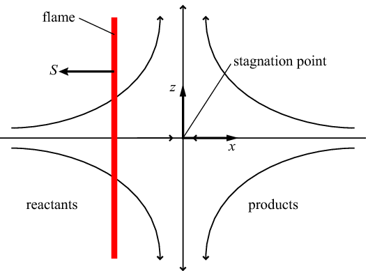
Schematic of the single opposed-jet flame
The simplest configuration for the elemental flame is that of the single opposed-jet flame [#Marzouk1999], [#Marzouk2003]. Fluid flows from \(x=\pm\infty\) toward the stagnation point at \(x=0\). The potential flow velocity field for the non-reacting flow is
where \(u\) and \(v\) are the velocity components in the \(z\) and \(x\) directions, respectively, and \(a(t)\) is the time varying strain rate parameter. If we take the mixture coming from \(x=-\infty\) to be premixed reactants and the mixture coming from \(x=+\infty\) to be the reaction products, a flame will be established at some point \(x<0\) where the consumption speed balances the local fluid velocity. Note that a flame in this configuration can never be completely extinguished because there will always be a region of contact between reactants and products.
Twin Opposed-Jet Flame

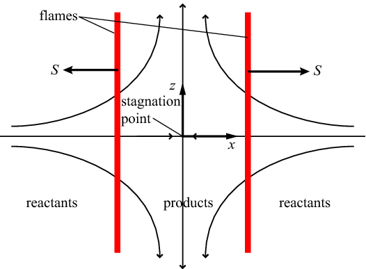
Schematic of the twin opposed-jet flame
The potential flow velocity field for the twin opposed-jet flame is identical to that of the single opposed jet flame, but with both inlet streams consisting of premixed reactants. As depicted above, two flames are established, one on each side of the stagnation point, propagating away from one another. Combustion products exist in the region between the two flames. Because the composition of the products mixture is not imposed externally, this configuration allows flame extinction to occur when the flames are pushed close together (at high strain rates). The domain is symmetric about the stagnation plane \(x=0\), allowing this configuration to be simulated numerically as a single flame with a symmetry boundary condition applied at the stagnation point.
Tubular Flame at Zero Stagnation Radius

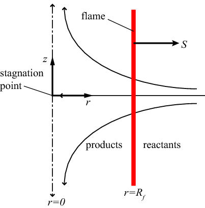
Schematic of the tubular flame at zero stagnation radius
The curved flame at zero stagnation radius is quite similar to the twin opposed-jet flame. Instead of the planar stagnation flow, we have an axisymmetric stagnation flow, with reactants flowing inward from \(r=\infty\) toward the stagnation point at \(r=0\), establishing a cylindrical flame propagating away from the centerline. The potential flow velocity field is:
where \(u\) and \(v\) are the velocity components in the \(z\) and \(r\) directions, respectively. As in the twin opposed jet flame, a symmetry boundary condition applies at \(r=0\), and flame extinction occurs when the flame is pushed too close to the centerline.
Tubular Flame at Finite Stagnation Radius

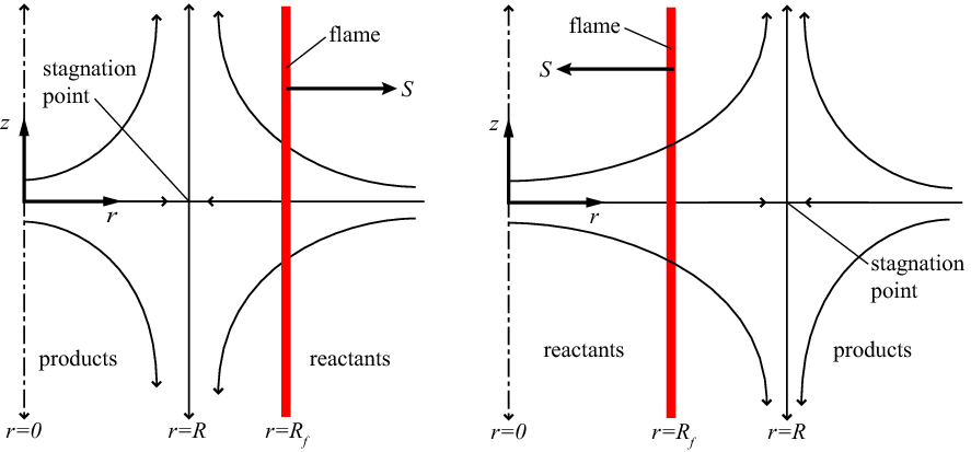
The tubular flame at zero stagnation radius can be modified by introducing a line source at \(r=0\). This produces a potential flow where the stagnation surface is a cylinder of radius \(R\), as shown above. Since the composition of the flow coming from \(r=0\) may be freely specified, this configuration permits both positively and negatively curved flames. The resulting potential flow velocity field is:
The boundary condition at \(r=0\) requires special attention in order to capture both the symmetry condition and the effect of the mass flux at the centerline.
Unified Formulation
The stagnation point flow configurations discussed above can be rewritten in a unified form, permitting both planar and curved geometry through the introduction of the parameter \(\alpha\) where \(\alpha=0\) for planar geometry and \(\alpha=1\) for curved geometry. We introduce the coordinate system \((r, z)\) where \(r\) is the coordinate normal to the flame (regardless of whether the coordinate system is curved or planar) and the \(z\) coordinate is tangential to the flame. The potential flow velocity field is then:
This formulation permits the use of a fictitious negative stagnation point radius \(R\), with the centerline acting as a sink rather than a source.
The stretch rate \(\kappa\) for a flame at radius \(R_{f}\) is:
When the flame is stationary, the stretch rate reduces to \(\kappa=a\) and thus curvature does not contribute to flame stretch for stationary flames in this configuration.